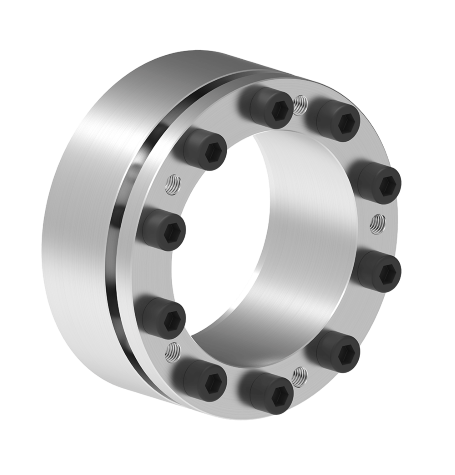

Locking Assemblies RfN 7013.0
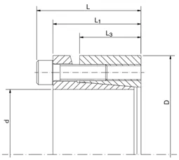
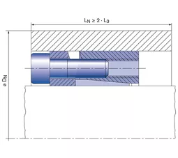
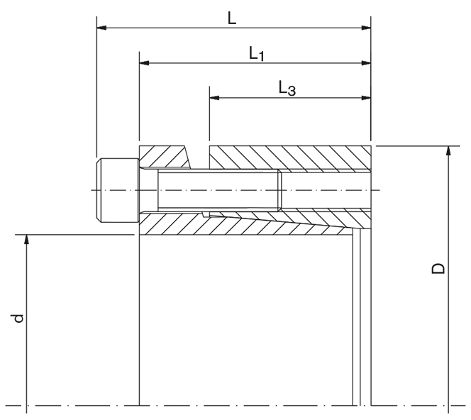
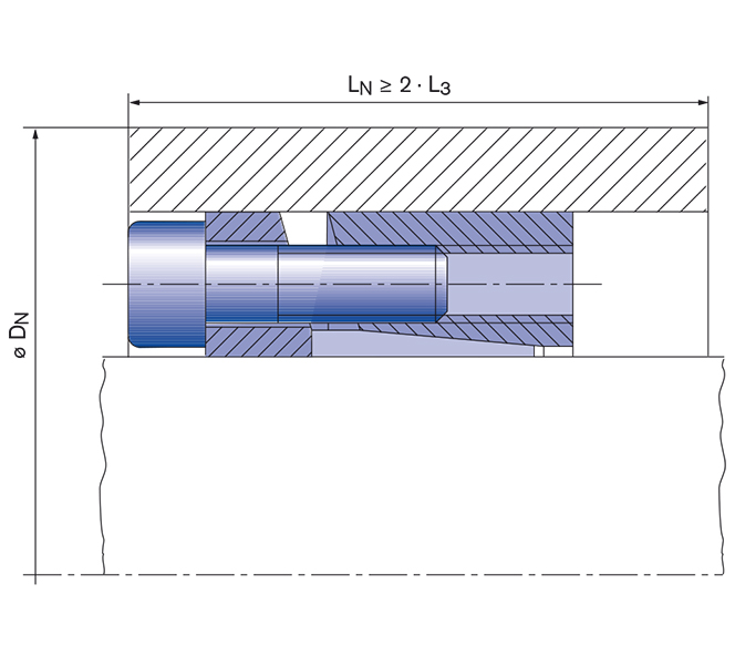
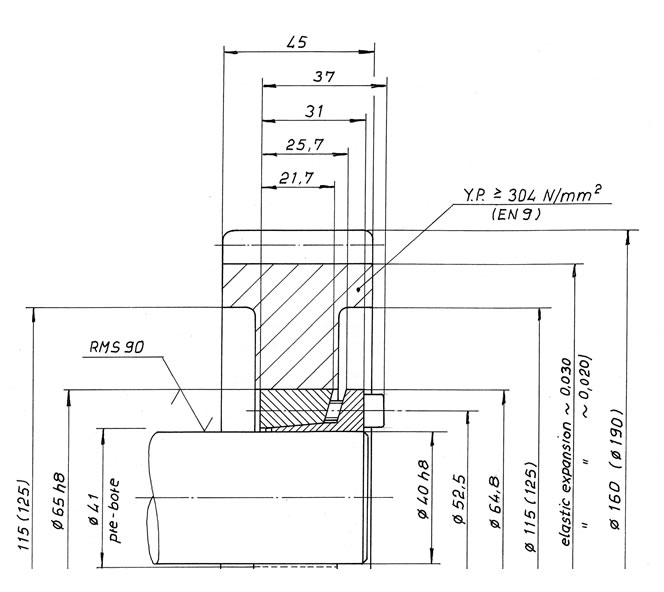
These Locking Assemblies are of single-taper design with a self-locking taper providing good self-centering action and concentricity, as well as increased torque capacity. A pre-centering hub section is not required. Integral push-off screws for disassembly are provided. This unit can be placed deep inside a bore due to it’s design. Available sizes: Metric series shafts from 20 mm to 150 mm dia. and Inch series for shafts from 1” to 4” diameter.
ℹ This series is also available in true inch sizes.
Technical Data & CAD Models
| CAD |
d
mm |
D
mm |
L
mm |
L1
mm |
L3
mm |
T
Nm |
pW
N/mm2 |
pN
N/mm2 |
DG
mm |
TA
Nm |
DN min bei Rp0,2 400 N/mm2
mm |
Tmax
Nm |
|---|---|---|---|---|---|---|---|---|---|---|---|---|
| 19 | 47 | 37 | 31 | 21,7 | 285 | 300 | 90 | 6 | 17 | 57 | 320 | |
| 20 | 47 | 37 | 31 | 21,7 | 300 | 290 | 90 | 6 | 17 | 57 | 340 | |
| 22 | 47 | 37 | 31 | 21,7 | 330 | 260 | 90 | 6 | 17 | 57 | 370 | |
| 24 | 50 | 37 | 31 | 21,7 | 420 | 300 | 110 | 6 | 17 | 63 | 480 | |
| 25 | 50 | 37 | 31 | 21,7 | 440 | 290 | 110 | 6 | 17 | 63 | 500 | |
| 28 | 55 | 37 | 31 | 21,7 | 490 | 260 | 100 | 6 | 17 | 68 | 560 | |
| 30 | 55 | 37 | 31 | 21,7 | 530 | 240 | 100 | 6 | 17 | 68 | 600 | |
| 32 | 60 | 37 | 31 | 21,7 | 740 | 270 | 110 | 6 | 17 | 75 | 850 | |
| 35 | 60 | 37 | 31 | 21,7 | 810 | 250 | 110 | 6 | 17 | 75 | 930 | |
| 38 | 65 | 37 | 31 | 21,7 | 890 | 230 | 100 | 6 | 17 | 80 | 1020 | |
| 40 | 65 | 37 | 31 | 21,7 | 940 | 220 | 100 | 6 | 17 | 80 | 1080 | |
| 42 | 75 | 46 | 38 | 25,3 | 1730 | 300 | 130 | 8 | 41 | 100 | 1980 | |
| 45 | 75 | 46 | 38 | 25,3 | 1860 | 290 | 130 | 8 | 41 | 100 | 2130 | |
| 48 | 80 | 46 | 38 | 25,3 | 1980 | 270 | 130 | 8 | 41 | 105 | 2270 | |
| 50 | 80 | 46 | 38 | 25,3 | 2070 | 260 | 130 | 8 | 41 | 105 | 2380 | |
| 55 | 85 | 46 | 38 | 25,3 | 2540 | 270 | 140 | 8 | 41 | 114 | 2920 | |
| 60 | 90 | 46 | 38 | 25,3 | 2770 | 250 | 130 | 8 | 41 | 118 | 3180 | |
| 65 | 95 | 46 | 38 | 25,3 | 3580 | 260 | 140 | 8 | 41 | 128 | 4110 | |
| 70 | 110 | 60 | 50 | 33,4 | 5100 | 240 | 130 | 10 | 83 | 144 | 5860 | |
| 75 | 115 | 60 | 50 | 33,4 | 5460 | 230 | 120 | 10 | 83 | 148 | 6270 | |
| 80 | 120 | 60 | 50 | 33,4 | 5850 | 210 | 110 | 10 | 83 | 152 | 6720 | |
| 85 | 125 | 60 | 50 | 33,4 | 7450 | 230 | 130 | 10 | 83 | 164 | 8560 | |
| 90 | 130 | 60 | 50 | 33,4 | 7900 | 220 | 120 | 10 | 83 | 168 | 9080 | |
| 95 | 135 | 60 | 50 | 33,4 | 9900 | 260 | 150 | 10 | 83 | 185 | 11380 | |
| 100 | 145 | 68 | 58 | 40,8 | 11000 | 190 | 110 | 10 | 83 | 184 | 12650 | |
| 110 | 155 | 68 | 58 | 40,8 | 12100 | 180 | 110 | 10 | 83 | 194 | 13910 | |
| 120 | 165 | 68 | 58 | 40,8 | 15700 | 190 | 120 | 10 | 83 | 212 | 18050 | |
| 130 | 180 | 77 | 65 | 45,4 | 20700 | 190 | 120 | 12 | 145 | 231 | 23800 | |
| 140 | 190 | 77 | 65 | 45,4 | 22500 | 180 | 110 | 12 | 145 | 241 | 25870 | |
| 150 | 200 | 77 | 65 | 45,4 | 28500 | 200 | 130 | 12 | 145 | 262 | 32770 |
| CAD |
d inch |
D inch |
L inch |
L1 inch |
L3 inch |
T ft-lbs |
pW psi |
pN psi |
DG mm |
TA ft-lbs |
DN min bei Rp0,2 400 N/mm2 inch |
|---|---|---|---|---|---|---|---|---|---|---|---|
| 1 | 1.969 | 1.457 | 1.220 | 0.854 | 323 | 40170 | 15070 | 6 | 13 | 2.398 | |
| 1 3/16 | 2.165 | 1.457 | 1.220 | 0.854 | 385 | 33800 | 13650 | 6 | 13 | 2.587 | |
| 1 1/4 | 2.362 | 1.457 | 1.220 | 0.854 | 531 | 38560 | 15070 | 6 | 13 | 2.876 | |
| 1 3/8 | 2.362 | 1.457 | 1.220 | 0.854 | 585 | 35055 | 15070 | 6 | 13 | 2.876 | |
| 1 7/16 | 2.559 | 1.457 | 1.220 | 0.854 | 620 | 33495 | 13935 | 6 | 13 | 3.069 | |
| 1 1/2 | 2.559 | 1.457 | 1.220 | 0.854 | 647 | 32100 | 13935 | 6 | 13 | 3.069 | |
| 1 5/8 | 2.953 | 1.811 | 1.496 | 0.996 | 1234 | 43870 | 19055 | 8 | 30 | 3.796 | |
| 1 3/4 | 2.953 | 1.811 | 1.496 | 0.996 | 1329 | 40740 | 19055 | 8 | 30 | 3.796 | |
| 1 7/8 | 3.150 | 1.811 | 1.496 | 0.996 | 1426 | 38070 | 17915 | 8 | 30 | 3.986 | |
| 1 15/16 | 3.150 | 1.811 | 1.496 | 0.996 | 1473 | 36840 | 17915 | 8 | 30 | 3.986 | |
| 2 | 3.150 | 1.811 | 1.496 | 0.996 | 1521 | 35690 | 17915 | 8 | 30 | 3.986 | |
| 2 1/8 | 3.346 | 1.811 | 1.496 | 0.996 | 1803 | 39125 | 19625 | 8 | 30 | 4.335 | |
| 2 3/16 | 3.346 | 1.811 | 1.496 | 0.996 | 1856 | 38005 | 19625 | 8 | 30 | 4.335 | |
| 2 1/4 | 3.543 | 1.811 | 1.496 | 0.996 | 1908 | 36875 | 18485 | 8 | 30 | 4.518 | |
| 2 3/8 | 3.543 | 1.811 | 1.496 | 0.996 | 2014 | 34935 | 18485 | 8 | 30 | 4.518 | |
| 2 7/16 | 3.740 | 1.811 | 1.496 | 0.996 | 2466 | 38965 | 20050 | 8 | 30 | 4.873 | |
| 2 1/2 | 3.740 | 1.811 | 1.496 | 0.996 | 2530 | 37990 | 20050 | 8 | 30 | 4.873 | |
| 2 9/16 | 3.740 | 1.811 | 1.496 | 0.996 | 2593 | 37065 | 20050 | 8 | 30 | 4.873 | |
| 2 3/4 | 4.331 | 2.362 | 1.969 | 1.315 | 3680 | 34770 | 18200 | 10 | 61 | 5.502 | |
| 2 7/8 | 4.528 | 2.362 | 1.969 | 1.315 | 3845 | 33300 | 16920 | 10 | 61 | 5.653 | |
| 2 15/16 | 4.528 | 2.362 | 1.969 | 1.315 | 3929 | 32590 | 16920 | 10 | 61 | 5.653 | |
| 3 | 4.528 | 2.362 | 1.969 | 1.315 | 4012 | 31910 | 16920 | 10 | 61 | 5.653 | |
| 3 3/8 | 4.921 | 2.362 | 1.969 | 1.315 | 5434 | 32430 | 18345 | 10 | 61 | 6.264 | |
| 3 7/16 | 5.118 | 2.362 | 1.969 | 1.315 | 5543 | 31810 | 17630 | 10 | 61 | 6.451 | |
| 3 1/2 | 5.118 | 2.362 | 1.969 | 1.315 | 5644 | 31240 | 17630 | 10 | 61 | 6.451 | |
| 3 3/4 | 5.315 | 2.362 | 1.969 | 1.315 | 7180 | 36450 | 21190 | 10 | 61 | 7.036 | |
| 3 15/16 | 5.709 | 2.677 | 2.283 | 1.606 | 7957 | 27300 | 16210 | 10 | 61 | 7.059 | |
| 4 | 5.709 | 2.677 | 2.283 | 1.606 | 8083 | 26870 | 16210 | 10 | 61 | 7.059 |
Images & Drawings
Product Characteristics
- Excellent concentricity and very easy to dismantle – these Locking Assemblies provide particularly good concentricity between the clamped parts. The flange is reinforced at the critical point. This prevents a bending and lifting of the inner ring during installation and therefore a good dismantling is ensured.
- High rotation speed – the Locking Assemblies remain true-to-form during assembly and so they are suitable in applications with higher rotational speeds.
- High radial loads – the material strength of the RfN 7013 Locking Assemblies makes them especially suitable for applications with high radial loads.
Example applications
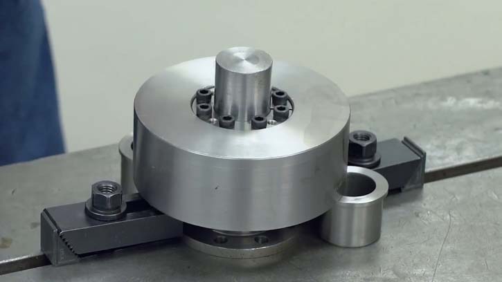
- crane running wheels
- couplings
- gearwheels
- flywheels
- fan wheels
Mounting of Locking Assembly
The Locking Assemblies are supplied slightly oiled and ready-to-use. The values for T, Fax, pW and pN apply to Locking Assemblies in delivery condition.
Surface finishes
For shafts and hub bores Ra = 1,6 μm
Tolerances
We recommend the following mounting tolerances
Shaft: h8; Hub: H8
Change of screw tightening torques
A change of the TA-values given in the above table is not admissible.
Downloads

Product Paper RINGFEDER® Locking Assemblies

Tech Paper Locking Assemblies RINGFEDER® RfN 7013.0
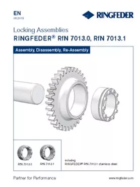
Instruction Manual Locking Assemblies RINGFEDER® RfN 7013.0, RfN 7013.1
Further downloads including certificates, instruction manuals and product images are available to you in our Download Center:
DownloadsSuitable Industry Solutions
Your Contact to Us
You like to have specific questions, require technical support or you are interested in a customized solution? Our experts in Engineering and Sales are more than happy to assist you. We look forward to your inquiry! Because excellent solutions always start with excellent guidance.
Contact us quickly and easily via our request form, by e-mail or telephone, or also using the "Need Help?" feature at the bottom right of this site.

