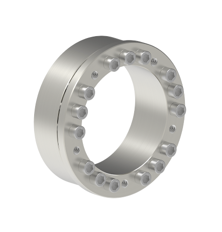

Locking Assemblies RfN 7013.1 Stainless Steel
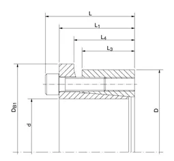
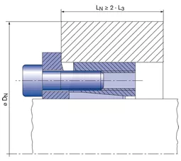
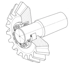
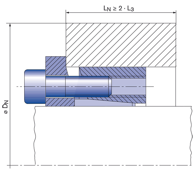
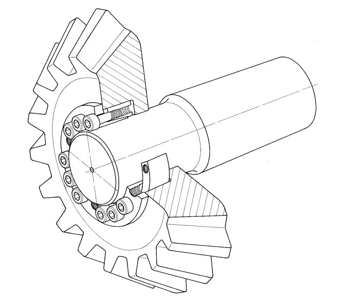
These flange type units is made of stainless steel and fix the hub positively against their extended flange preventing axial movement during tightening. Applied wherever self-centering action and good concentricity of mounted components are essential and hubs with straight-thru bores are used. Available sizes: Metric series shafts from 20 mm to 150 mm dia. and Inch series for shafts from 1” to 4” diameter.
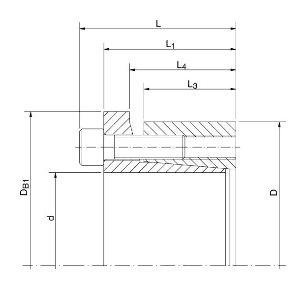
Technical Data & CAD Models
| CAD |
d
mm |
D
mm |
DB1
mm |
L
mm |
L1
mm |
L4
mm |
T
Nm |
pW
N/mm2 |
pN
N/mm2 |
TA
Nm |
|---|---|---|---|---|---|---|---|---|---|---|
| 19 | 47 | 53 | 37 | 31 | 25,7 | 199 | 232 | 69 | 14 | |
| 20 | 47 | 53 | 37 | 31 | 25,7 | 210 | 224 | 69 | 14 | |
| 22 | 47 | 53 | 37 | 31 | 25,7 | 231 | 201 | 69 | 14 | |
| 24 | 50 | 56 | 37 | 31 | 25,7 | 294 | 201 | 69 | 14 | |
| 25 | 50 | 56 | 37 | 31 | 25,7 | 308 | 224 | 85 | 14 | |
| 28 | 55 | 62 | 37 | 31 | 25,7 | 343 | 201 | 77 | 14 | |
| 30 | 55 | 62 | 37 | 31 | 25,7 | 371 | 186 | 77 | 14 | |
| 32 | 60 | 68 | 37 | 31 | 25,7 | 518 | 209 | 85 | 14 | |
| 35 | 60 | 68 | 37 | 31 | 25,7 | 567 | 193 | 85 | 14 | |
| 38 | 65 | 73 | 37 | 31 | 25,7 | 623 | 178 | 77 | 14 | |
| 40 | 65 | 73 | 37 | 31 | 25,7 | 685 | 170 | 77 | 14 | |
| 42 | 75 | 83 | 46 | 38 | 30,3 | 1211 | 232 | 100 | 34 | |
| 45 | 75 | 83 | 46 | 38 | 30,3 | 1302 | 217 | 100 | 34 | |
| 48 | 80 | 88 | 46 | 38 | 30,3 | 1386 | 209 | 100 | 34 | |
| 50 | 80 | 88 | 46 | 38 | 30,3 | 1449 | 201 | 100 | 34 | |
| 55 | 85 | 95 | 46 | 38 | 30,3 | 1778 | 209 | 108 | 34 | |
| 60 | 90 | 100 | 46 | 38 | 30,3 | 1939 | 193 | 100 | 34 | |
| 65 | 95 | 105 | 46 | 38 | 30,3 | 2506 | 201 | 108 | 34 | |
| 70 | 110 | 120 | 60 | 50 | 40,4 | 3570 | 186 | 100 | 66 | |
| 75 | 115 | 125 | 60 | 50 | 40,4 | 3822 | 178 | 93 | 66 | |
| 80 | 120 | 130 | 60 | 50 | 40,4 | 4095 | 162 | 85 | 66 | |
| 85 | 125 | 135 | 60 | 50 | 40,4 | 5215 | 178 | 100 | 66 | |
| 90 | 130 | 140 | 60 | 50 | 40,4 | 5530 | 170 | 93 | 66 | |
| 95 | 135 | 145 | 60 | 50 | 40,4 | 6930 | 201 | 116 | 66 | |
| 100 | 145 | 155 | 68 | 58 | 47,8 | 7700 | 147 | 85 | 66 | |
| 110 | 155 | 165 | 68 | 58 | 47,8 | 8470 | 139 | 85 | 66 | |
| 120 | 165 | 175 | 68 | 58 | 47,8 | 10990 | 147 | 93 | 66 | |
| 130 | 180 | 190 | 77 | 65 | 52,4 | 14490 | 147 | 93 | 115 | |
| 140 | 190 | 200 | 77 | 65 | 52,4 | 15750 | 139 | 85 | 115 | |
| 150 | 200 | 210 | 77 | 65 | 52,4 | 19950 | 155 | 100 | 115 |
| CAD |
d inch |
D inch |
DB1 inch |
L inch |
L1 inch |
L4 inch |
T ft-lbs |
pW psi |
pN psi |
TA ft-lbs |
|---|---|---|---|---|---|---|---|---|---|---|
| 0.748 | 1.850 | 2.087 | 1.457 | 1.220 | 1.012 | 147 | 33623 | 10000 | 10 | |
| 0.787 | 1.850 | 2.087 | 1.457 | 1.220 | 1.012 | 155 | 32464 | 10000 | 10 | |
| 0.866 | 1.850 | 2.087 | 1.457 | 1.220 | 1.012 | 170 | 29130 | 10000 | 10 | |
| 0.945 | 1.969 | 2.205 | 1.457 | 1.220 | 1.012 | 217 | 29130 | 10000 | 10 | |
| 0.984 | 1.969 | 2.205 | 1.457 | 1.220 | 1.012 | 227 | 32464 | 12319 | 10 | |
| 1.102 | 2.165 | 2.441 | 1.457 | 1.220 | 1.012 | 253 | 29130 | 11159 | 10 | |
| 1.181 | 2.165 | 2.441 | 1.457 | 1.220 | 1.012 | 274 | 26957 | 11159 | 10 | |
| 1.260 | 2.362 | 2.677 | 1.457 | 1.220 | 1.012 | 382 | 30290 | 12319 | 10 | |
| 1.378 | 2.362 | 2.677 | 1.457 | 1.220 | 1.012 | 418 | 27971 | 12319 | 10 | |
| 1.496 | 2.559 | 2.874 | 1.457 | 1.220 | 1.012 | 460 | 25797 | 11159 | 10 | |
| 1.575 | 2.559 | 2.874 | 1.457 | 1.220 | 1.012 | 505 | 24638 | 11159 | 10 | |
| 1.654 | 2.953 | 3.268 | 1.811 | 1.496 | 1.193 | 893 | 33623 | 14493 | 25 | |
| 1.772 | 2.953 | 3.268 | 1.811 | 1.496 | 1.193 | 960 | 31449 | 14493 | 25 | |
| 1.890 | 3.150 | 3.465 | 1.811 | 1.496 | 1.193 | 1022 | 30290 | 14493 | 25 | |
| 1.969 | 3.150 | 3.465 | 1.811 | 1.496 | 1.193 | 1069 | 29130 | 14493 | 25 | |
| 2.165 | 3.346 | 3.740 | 1.811 | 1.496 | 1.193 | 1311 | 30290 | 15652 | 25 | |
| 2.362 | 3.543 | 3.937 | 1.811 | 1.496 | 1.193 | 1430 | 27971 | 14493 | 25 | |
| 2.559 | 3.740 | 4.134 | 1.811 | 1.496 | 1.193 | 1848 | 29130 | 15652 | 25 | |
| 2.756 | 4.331 | 4.724 | 2.362 | 1.969 | 1.591 | 2633 | 26957 | 14493 | 49 | |
| 2.953 | 4.528 | 4.921 | 2.362 | 1.969 | 1.591 | 2819 | 25797 | 13478 | 49 | |
| 3.150 | 4.724 | 5.118 | 2.362 | 1.969 | 1.591 | 3020 | 23478 | 12319 | 49 | |
| 3.346 | 4.921 | 5.315 | 2.362 | 1.969 | 1.591 | 3846 | 25797 | 14493 | 49 | |
| 3.543 | 5.118 | 5.512 | 2.362 | 1.969 | 1.591 | 4079 | 24638 | 13478 | 49 | |
| 3.740 | 5.315 | 5.709 | 2.362 | 1.969 | 1.591 | 5111 | 29130 | 16812 | 49 | |
| 3.937 | 5.709 | 6.102 | 2.677 | 2.283 | 1.882 | 5679 | 21304 | 12319 | 49 | |
| 4.331 | 6.102 | 6.496 | 2.677 | 2.283 | 1.882 | 6247 | 20145 | 12319 | 49 | |
| 4.724 | 6.496 | 6.890 | 2.677 | 2.283 | 1.882 | 8106 | 21304 | 13478 | 49 | |
| 5.118 | 7.087 | 7.480 | 3.031 | 2.559 | 2.063 | 10687 | 21304 | 13478 | 85 | |
| 5.512 | 7.480 | 7.874 | 3.031 | 2.559 | 2.063 | 11617 | 20145 | 12319 | 85 | |
| 5.906 | 7.874 | 8.268 | 3.031 | 2.559 | 2.063 | 14715 | 22464 | 14493 | 85 |
Images & Drawings
Product Characteristics
- Excellent concentricity and very easy to dismantle – these Locking Assemblies provide particularly good concentricity between the clamped parts. The flange is reinforced at the critical point, preventing bending or lifting of the inner ring during assembly and thereby ensuring easy dismantling.
- High rotation speed – the dimensional accuracy of the RfN 7013 Locking Assemblies allows their use in applications with higher rotational speeds.
- High radial loads – the material strength of the RfN 7013 Locking Assemblies makes them especially suitable for applications with high radial loads.
- Axial hub positioning – the increased outer diameter of the flange prevents the axial movement of the hub during assembly, and improves the run-out ability of the Locking Assembly.
- High torque – the increased number of clamping screws ensures the same transmission values as the RfN 7013.0.
Mounting of Locking Assembly
The Locking Assemblies are supplied slightly oiled and ready-to-use. The values for T, Fax, pW and pN apply to Locking Assemblies in delivery condition.
Surface finishes
For shafts and hub bores Ra = 1,6 μm
Tolerances
We recommend the following mounting tolerances
Shaft: h8; Hub: H8
Arrangement of several Locking Assemblies RfN 7013.1
Arrangement only possible from 2 sides. If several Locking Assemblies are used to increase the transmission values the clamping systematization has to be considered.
Change of screw tightening torques
A change of the TA-values given in the above table is not admissible.
Downloads

Product Paper RINGFEDER® Locking Assemblies

Tech Paper Locking Assemblies RINGFEDER® RfN 7013.1 stainless steel
Instruction Manual Locking Assemblies RINGFEDER® RfN 7013.0, RfN 7013.1
Further downloads including certificates, instruction manuals and product images are available to you in our Download Center:
DownloadsSuitable Industry Solutions
Your Contact to Us
You like to have specific questions, require technical support or you are interested in a customized solution? Our experts in Engineering and Sales are more than happy to assist you. We look forward to your inquiry! Because excellent solutions always start with excellent guidance.
Contact us quickly and easily via our request form, by e-mail or telephone, or also using the "Need Help?" feature at the bottom right of this site.

